
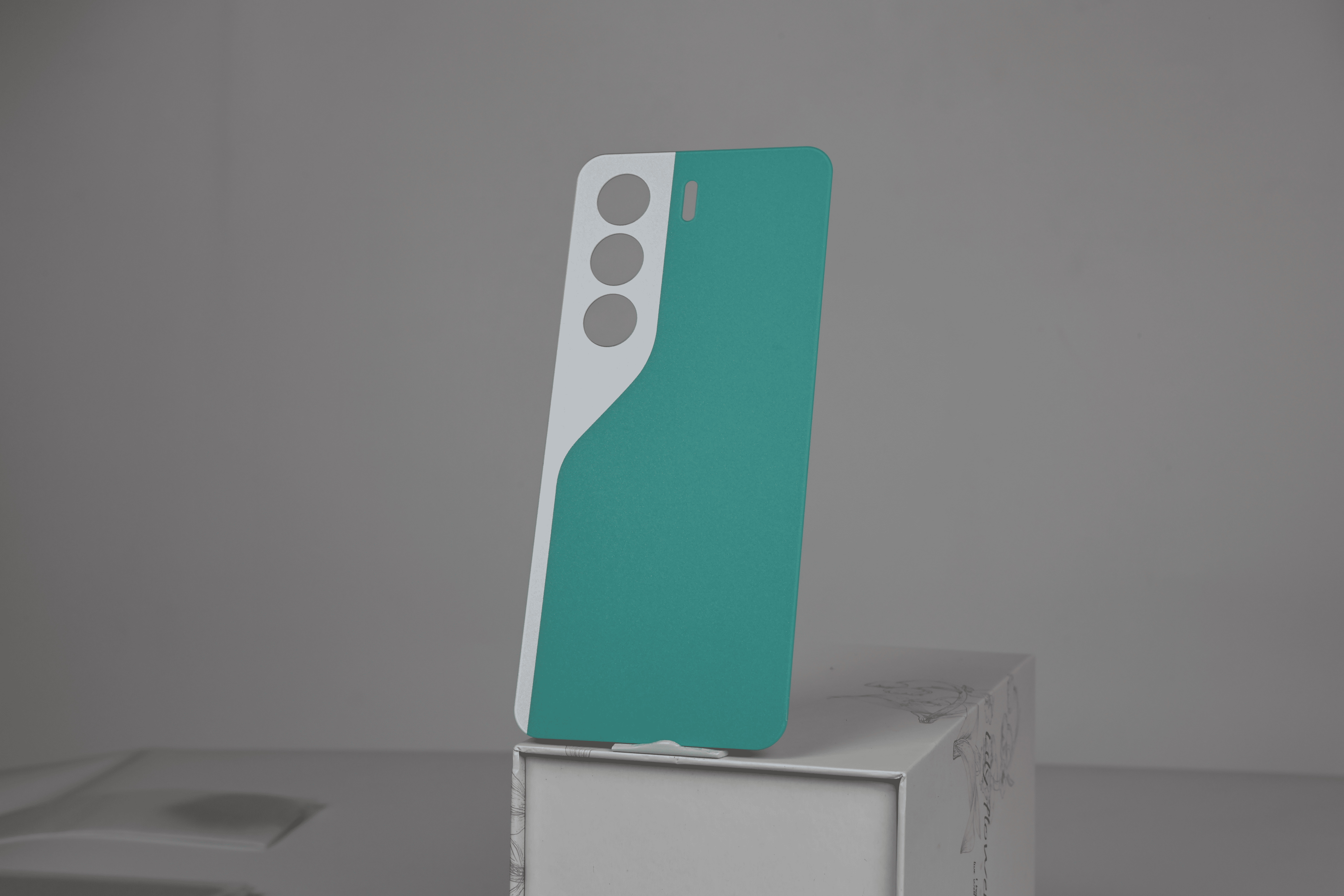
A buyer-side guide to 0.55 mm glass back covers — what thinness actually buys, what it costs, which decorative finishes can sit over a charging coil, how to test "Qi compatible" instead of trusting the phrase, and what to write into the RFQ.
A 0.55 mm back cover is a strange product to buy, because the number in the specification is not the thing being sold. What the brand is buying is a cover that makes the phone feel original, still charges at full speed on a pad, and does not crack when a corner meets a table edge. The 0.55 mm is just the number that makes all three possible — or, if it is specified carelessly, the number that quietly breaks one of them. This guide is written for the buyer who has to choose the thickness, choose the finish, and then prove both were right.
1. Is 0.55 mm Thin Enough — and Thin Enough for What?
Buyers usually arrive at this question with a number already in mind, usually the thickness of the original cover they are replacing. That is the right instinct, but it is only one of three references the thickness has to satisfy. A slim cover is measured against the phone it replaces, against the charging stack it has to sit on top of, and against the strength budget of the programme. Miss any one of them and the specification looks fine on paper and fails in the field.
Against the phone, thinness is a fit question. A replacement cover that is 0.2 mm thicker than the original changes how the frame sits, how a case closes, and how the camera bump reads in the hand. Against the charging stack, thinness is a distance question, and distance is the single most important variable in wireless power transfer — more important than the glass grade, the coating, or the brand of the coil. Against strength, thinness is a margin question: every tenth of a millimetre removed from the section is a tenth of a millimetre of stiffness you no longer have, and glass does not forgive a thin edge.
The RT-L3001 platform is a useful reference point because its published record is specific. It is a tempered glass back cover at 168.14 mm by 75.14 mm by 0.55 mm, described as Qi wireless charging compatible, anti-fingerprint and anti-slip, waterproof and dustproof, with OEM craftsmanship and customizable colours and surface treatments — including AG, holographic and sky mirror finishes across a palette of more than twenty options.
| Model | RT-L3001 |
| Product name | Tempered Glass Back Cover — Slim, Wireless Charging Compatible |
| Dimensions | 168.14 mm (L) × 75.14 mm (W) × 0.55 mm (T) |
| Charging | Qi wireless charging compatible |
| Surface | Anti-fingerprint and anti-slip; AG, holographic and sky mirror textures among 20+ colour and texture options |
| Claimed protection | Waterproof and dustproof (assembly-dependent — see section 10) |
| Certification | ISO 9001 |
| Packaging | Standard: pearl cotton bag + cardboard box. Reinforced: pearl cotton bag + PE bag + desiccant + foam box + carton |
| Minimum order | 1 unit on the listing |
| Customisation | Colours and surface treatments customizable |
What the table does not tell you — because no product page can — is what happens when those three references conflict. That is the actual job. The rest of this guide takes them one at a time, and then shows how to write the result into a purchase order so that the factory and the brand are measuring the same thing.
2. What Actually Sits Between the Coil and the Pad
If you take one thing from this article, take this: the glass is rarely the problem. The stack is. Between the transmitter coil in the pad and the receiver coil in the phone there are, in order, the pad surface, an air gap, your cover glass, the adhesive layer, whatever thermal or shielding material sits inside the phone, and the receiver coil itself. Every layer adds distance, and Qi transfer efficiency falls as that distance grows.
This is why a 0.55 mm cover can outperform a 0.8 mm cover by a wider margin than the 0.25 mm difference suggests: the gain is not linear, because the system is already operating near the edge of its working range. It is also why a beautifully thin cover can still charge badly — if the decorative layer underneath it contains metal, the field is attenuated before thickness even matters.
Ask your supplier to draw the stack. Not a marketing diagram, an engineering one, with a nominal dimension and a tolerance for each layer, from the outside surface of the glass to the receiver coil. If they cannot produce it, they are selling glass, not a charging solution. If they can, you have the document you need to argue about efficiency later without guessing. The broader relationship between material choice, spacing and thermal behaviour is covered in our guide to how back cover materials affect charging efficiency and heat.
3. How Much Efficiency Does the Glass Itself Cost?
Less than most buyers assume, and less than most suppliers claim. At the frequencies Qi uses, glass is a dielectric with low absorption; a 0.55 mm sheet does not meaningfully block a magnetic field, and its own losses are small compared with the losses caused by spacing and misalignment. Chemically strengthened glass behaves the same way electrically as ordinary glass — the strengthening is an ion-exchange treatment in the surface, not a metallic coating.
So where does the loss come from? Three places, in descending order of impact. First, distance, including the thickness of any case the user adds. Second, alignment: a coil offset by a few millimetres loses more than a coil separated by an extra tenth of a millimetre. Third, conductive material in the decoration, which is the one buyers most often miss because it is invisible and it is chosen for appearance, not electrical performance.
That third point deserves its own section, because it is where a slim cover programme most often goes wrong.
4. Which of the 20+ Finishes Can Safely Sit Over a Coil?
A finish is not a colour. It is a thin-film stack, and the stack either contains metal or it does not. That single fact decides whether the finish belongs on the outside of a wireless charging cover, on the outside of a non-charging cover, or nowhere near either.
Anti-glare finishes are typically produced by etching or by a silica-based coating. Both are dielectric, and both are routinely used over charging coils. Frosted and textured finishes work the same way, and are worth reading about in the context of frosted versus glossy surface selection if grip is part of the brief. Holographic effects are usually built from an embossed micro-structured layer, which is also dielectric — but the layer beneath it may be a reflective coating, and that is where the question starts.
Mirror-like finishes are the ones to interrogate. A "sky mirror" or chrome-effect surface is often produced by vacuum metallizing or by a metallic pigment in the print, and a continuous metal film a few tens of nanometres thick is enough to attenuate a magnetic field. It does not have to be thick to cause a problem; it has to be continuous. The practical resolution is not to ban the finish but to ask for the construction and then test the finished part, not a bare glass sample.
| Finish family | What it usually is | What to ask before approving |
| AG / matte | Etched glass or silica coating; dielectric | Haze and gloss targets; whether the etch is on the outer surface only |
| Frosted / textured | Moulded or etched texture; dielectric | Texture depth consistency batch to batch; grip after abrasion |
| Holographic | Embossed micro-structure, sometimes over a reflective layer | Whether a reflective layer sits under the structure, and whether it is continuous across the coil area |
| Sky mirror / chrome | Often vacuum metallized or metallic-pigment print | Coating chemistry, thickness, and a charging test on the finished part |
| Solid colour print | Ink layer, usually dielectric | Pigment type; ink thickness tolerance; colour shift after coating |
The test is simple and you should insist on it: place the finished cover, decorated exactly as production will be, on a phone, on a pad, and measure delivered power. Do not accept a test on bare glass. The whole point of a finish is that it changes the surface; sometimes it changes the electrical behaviour too.
5. Does Thinner Glass Break More Easily?
Yes, if everything else stays the same — but everything else rarely does. The strength of a thin glass cover is dominated by two things that matter more than raw thickness: the compressive layer created by chemical strengthening, and the quality of the edge.
Chemical strengthening puts the surface into compression by exchanging small ions for larger ones in a hot salt bath. A well-controlled process produces a surface layer in the hundreds of megapascals of compression, and that layer is what stops a scratch from becoming a crack. A poorly controlled process produces a part that measures the right thickness and fails the first drop. The difference is invisible in a spec sheet and obvious in a drop test, which is why "tempered" should never be accepted as a description without a process name and a test result. The distinction between chemical strengthening and thermal tempering is set out in our article on how back cover manufacturing differs from screen protectors.
Edge quality is the second half. Glass fails in tension, and a cover bends, so the edge that is in tension during a corner drop is the edge that initiates the crack. A chipped edge, a rough grind, or a chamfer that is too small concentrates stress and turns a survivable impact into a fracture. A 0.55 mm part with a clean, correctly chamfered edge and a good compressive layer will outperform a 0.8 mm part with a poor edge almost every time.
So the buyer's question is not "is 0.55 mm strong enough" but "what evidence do I have that this supplier controls both variables". Ask for the strengthening process, the measured compressive stress and depth if available, the edge specification in the drawing, and a drop test on the finished, decorated part.
6. What "Wireless Charging Compatible" Must Mean in the Contract
On a product page, "compatible" is a claim. In a purchase order, it has to be a measurement. The gap between the two is where most disputes live, because a cover can be compatible and still charge slowly, or compatible on one phone and not on another.
Write the test, not the adjective. A workable protocol names the phone model, the charger model, the ambient temperature, the alignment positions tested, the duration, and the acceptance criterion — and it measures power delivered at the battery, not just whether the charging icon appears.
| Test item | How to define it in the PO |
| Reference devices | Name the exact phone model, the exact pad model, and the adapter wattage. Generic "Qi charger" is not a reference. |
| Alignment | Test at centre plus four offsets (for example 5 mm in each direction). Record power at each position, not an average. |
| Metric | Power delivered to the battery, measured by an inline meter, after a stabilisation period — not the pad's rated output. |
| Duration | Long enough to expose thermal derating — typically 30 minutes or more, reported at intervals. |
| Temperature | Ambient, plus surface temperature at the coil area at the end of the run. |
| Sample | State how many pieces, from how many production cavities or lots, and whether they are decorated. |
| Acceptance | A numeric floor (for example, no less than X W at centre and no less than Y W at maximum offset), agreed before the first sample is made. |
One caution on acceptance criteria: set the floor from the phone's own behaviour without your cover, not from the pad's marketing number. If the phone draws 12 W bare and 11.2 W with the cover, that is the real comparison. Comparing against 15 W rated output will fail every cover ever made.
7. Why the Same Cover Charges Fast on One Phone and Slowly on Another
Buyers sometimes report that a cover "works" in the sample room and generates complaints in the market. The cover did not change. The phone population did. Four mechanisms explain most of it.
Coil geometry mismatch. Receiver coils differ in diameter and position between models. A cover that adds 0.55 mm is adding it to every phone equally, but the penalty is larger on a phone whose coil already sits deep in the chassis.
Foreign object detection. A phone will refuse or reduce charging if it suspects metal in the field. A decorative layer that is conductive, or a metallic logo, can trigger this intermittently — which is exactly why the finished part must be tested, not the glass.
Thermal derating. Phones reduce charging power as they heat up. A cover that insulates slightly — and thicker covers, or covers with an added film, do — can push the phone into derating sooner. This is a slow effect, invisible in a two-minute test.
Case stacking. Many users put a case on top of the new cover. The case adds distance again, and a case with a magnet array adds a conductive and magnetic structure right in the field. If your product will be sold alongside a case, test the combination, not the cover alone.
8. What to Measure on the First Article
A first article inspection for a slim cover is not a visual check. It is a dimensional and functional report. The measurements below are the ones that actually predict field failures, in rough order of how much trouble they cause.
| Characteristic | Method | Why it matters |
| Thickness | Micrometer, at least 9 points across the panel | A single centre reading hides edge thinning and charge-height variation |
| Flatness / warpage | Surface plate and feeler gauge, or optical scan | Warp prevents full seating, which opens the coil gap unevenly |
| Length / width | CMM or calibrated gauge | Determines frame fit and case closure |
| Cut-out position | Optical comparator against drawing | Camera and sensor apertures are the least forgiving feature |
| Edge condition | Magnification, chip count and size against an AQL | Edge chips are the crack initiation sites |
| Coating thickness | Ellipsometer or cross-section | AF and hard coats lose function when thin, and cost when thick |
| Adhesion | Cross-hatch plus tape pull | Decoration lifting at the edge is the most common cosmetic return |
| Colour | Spectrophotometer, ΔE against a signed master | The only objective way to settle a colour argument |
| Charging performance | Protocol in section 6 | The functional reason the part exists |
Note what is absent: hardness pencils and drop tests on bare glass. Both are useful, but neither predicts whether the finished, decorated, assembled product will work. Insist that the report is generated on production-representative parts.
9. How to Approve 20+ Colours Without 20 Rounds of Sampling
A wide palette is a selling point and a project-management trap. Each additional finish is another approval loop, another chance of a batch mismatch, and another line in the quality agreement. The way to keep it manageable is to standardise the approval instrument rather than the colour.
Approve against a physical master, not a screen. Sign and date two sets of masters — one held by the factory, one by you — and treat them as the reference for the life of the programme. Measure with a spectrophotometer under a defined illuminant, and agree a ΔE tolerance in advance. A single number for all colours is usually wrong; dark, saturated and metallic finishes need different tolerances from pale ones.
Then control the things a colour meter cannot see: texture direction, gloss level, and the way a finish reads under different lighting. A holographic or AG surface can match numerically and still look wrong because the texture is oriented differently or the gloss is off. Approve those on a physical sample under at least two lighting conditions, and write the lighting conditions into the record so the next discussion has a shared reference.
For programmes with several SKUs, batch the approvals. Approve the construction once, then approve each colour as a variant of that construction. It is the construction — the layer stack, the coating, the texture — that carries the technical risk, and it is the same across the palette. Our notes on textured back cover options cover how finish choice interacts with grip and perceived quality.
10. What "Waterproof and Dustproof" Can Honestly Mean on a Replacement Cover
This is the claim most likely to be misunderstood on both sides of the transaction. Glass itself is impermeable. A phone is not sealed by glass; it is sealed by the adhesive bead or gasket that bonds the cover to the frame, by the fit of that cover to the frame geometry, and by every other opening in the product.
So a cover cannot be "waterproof" on its own. What can be specified is a cover that is compatible with a sealed assembly: the right adhesive system, the right surface energy for that adhesive, a flat bonding land, and a curing process that does not distort the part. The ingress protection belongs to the assembled phone, and it has to be tested on the assembled phone.
If a supplier claims an IP rating for a bare cover, ask what was tested. If the answer is a glass sample dipped in water, the claim is meaningless. If the answer is an assembled unit subjected to a defined test, ask for the report and the test conditions. This is not pedantry; it is the difference between a specification and a slogan, and it is the kind of question that separates a serious supplier from a trading company.
11. What Changes When the Cover Goes Inside a Case
Most slim covers end up inside a case, and the case changes the electrical problem more than the cover does. Two mechanisms matter.
The first is simple distance. A case adds a millimetre or two, and that is often more than the entire thickness of the cover. A programme that optimises the cover to 0.55 mm and then ships it with a 2 mm case has optimised the wrong variable.
The second is magnetic or metallic hardware in the case. Magnet arrays used for accessory attachment sit directly in the field, and their effect depends on geometry, polarity and placement. Some arrangements are benign; others reduce delivered power noticeably. If the product will be sold with a magnetic case, the only responsible test is the combination. Our guide to magnetic back cover compatibility goes further into alignment and accessory behaviour.
12. How 0.55 mm Panels Survive a Container
Thin glass fails in transit for reasons that have nothing to do with the glass: edge contact, point loads, stack pressure, and humidity. A carton that passes a drop test with a foam insert can still deliver chipped edges if the panels are allowed to move inside it.
The packaging options on this platform are a reasonable starting point for the conversation. Standard packing is a pearl cotton bag plus a cardboard box. Reinforced packing adds a PE bag, desiccant, a foam box and a carton. The difference between the two is not cosmetic: the reinforced route addresses humidity and shock separately, which is what a long sea freight lane actually requires.
| Packing level | Construction | Best suited to |
| Standard | Pearl cotton bag + cardboard box | Small orders, air freight, short transit, local distribution |
| Reinforced | Pearl cotton bag + PE bag + desiccant + foam box + carton | Sea freight, long transit, humid climates, multi-drop distribution |
Whichever level you choose, specify three things in the PO: the maximum number of panels per inner bundle, the drop height and orientation for the carton test, and the acceptable chip count on arrival. Without those, "good packaging" is an opinion. For a wider treatment of crating, interleaving and inbound inspection, see our guide to glass component packaging and shipping protection.
13. Where Buyers Lose Money on Slim Back Covers
Almost none of the losses come from the price per piece. They come from decisions that were not made, or were made late. These are the seven that repeat most often.
Treating "compatible" as a specification. Without a test protocol there is nothing to appeal to when the market complains, and no way to prove the cover is not the cause.
Approving a finish on bare glass. The decorated part is the product. A metallic decoration can change charging behaviour, and a coating can change adhesion and colour.
Leaving edge condition out of the drawing. If the edge is not specified, it is not controlled, and the crack initiation site is left to chance.
Approving colour under the wrong light. A match that holds in a meeting room and fails in daylight becomes a return, not a discussion.
Accepting an ingress claim for a component. As section 10 sets out, the seal belongs to the assembly; a claim on a bare cover cannot be verified and should not be repeated in marketing.
Not testing the case combination. The end user experiences cover plus case, and that is the configuration that should be validated.
Discovering the packing problem at destination. Edge chips found on arrival are expensive because the remedy — re-inspection or replacement — happens after freight, duty and time have been paid.
14. The RFQ Sheet We Would Send
If you are sourcing a slim charging cover and want a useful first reply rather than a catalogue, send the following. Most of it takes an afternoon to assemble, and it removes weeks of back-and-forth.
Device and fit. Phone model, the original cover thickness, and whether the cover is a replacement or an accessory. Include a drawing or a physical original if the fit is tight around the camera.
Charging requirement. The pad and adapter you will specify, the phone models you will claim compatibility for, and the delivered-power floor you consider acceptable.
Finish and colour. The finish family, a physical reference for colour, the gloss or haze target, and whether the finish will carry a logo. If a logo is involved, say whether it is printed, etched or applied as a metal badge — the last one has electrical consequences.
Durability and sealing. Drop height and surface, the adhesive system you intend to use, and whether the assembled product will be tested for ingress protection.
Quality and logistics. AQL for cosmetic defects, edge chip limits, packing level, panels per carton, marking and labelling requirements, and the destination port or warehouse.
A supplier who answers these questions with specific numbers is telling you something about how they work. A supplier who answers with adjectives is telling you something too.
15. Frequently Asked Questions
Does a 0.55 mm glass cover reduce wireless charging speed? The glass itself adds very little loss. What reduces speed is the total distance between coils, misalignment, heat, and any conductive material in the decoration or in a case. Measure the finished part on a real phone rather than assuming thickness alone decides it.
Can I put a metal logo on a charging cover? A small badge outside the coil area may be acceptable; a continuous metal film or a badge over the coil is likely to attenuate the field or trigger foreign object detection. Test the exact geometry before committing to artwork.
Is thinner always better for a replacement cover? No. Matching the original thickness usually matters more than minimising it, because fit, case closure and feel are all defined by the original. Go thinner than the original only if you have a reason and a strength margin to support it.
Can one cover fit several phone models? Only if the camera aperture, button cut-outs and overall dimensions coincide. Battery covers are model-specific parts; treating them as universal is one of the fastest routes to a high return rate.
What is the minimum order? The listing for RT-L3001 shows a minimum of one unit, which is typical for sample and small-batch work. Production quantities, tooling and colour minimums are programme-specific and should be confirmed in writing for your project rather than assumed from the listing.
Sourcing a Slim wireless charging back cover?
Send us the phone model, the charging requirement and the finish you have in mind. We manufacture tempered glass back covers at 0.55 mm with chemically strengthened edges and customisable colour and texture, and we will tell you plainly which finishes are safe over a coil — and which are not.